About this deal
isolation if you plan to power a device which is somehow connected to the mains as well. That way you wont fry your computer if your computer and the device are not on the same phase. ADD-RGB equipment can be compatible with 12V RGB motherboard via the convertor, to achieve synchronous lighting compatibility. For an input of 5v, the output of this IC’s can deliver a maximum of 800mA at 88% efficiency. For higher output current you have to increase the input voltage above 5 Volts.
Analog Devices MAX680 Datasheet and Product Info | Analog Devices
Put as much effort into your question as you'd expect someone to give in an answer"- @Princess Luna After the MOSFET is turned off, the magnetic field of the Inductor turns in to voltage spike and it goes through the Schottky diode. Hence this voltage spike will be exhibited as output in the circuit. As there is a capacitor in the output, it charges in every cycle of oscillation and keeps the voltage constant. In this voltage booster circuit components are used to boost 5v to 12v. Above all for MT3608 to start working, the EN pin should be tied to high. If you want to turn on and off the output with an external circuit you can use this pin. This circuit is capable of delivering 2A current to the Load. ADJUSTABLE OUTPUT VOLTAGE: Below schematic is implemented using variable output high efficiency IC MT3608. A compact and small form factor of this module/IC makes it possible to install this IC in size and weight imperative devices. Also works on very low current drawing loads contrary to its competitors. In this post we will be avoiding using the old school method and only focus on boost converters with simple ICs. Earlier methods or you can say older methods used transistors as a switching device externally and lots of components were required to implement it making it complex. That is the reason to go with ICs and modules. Also it will save a lot of time to center your attention towards the actual functioning of the project rather than the power supply.You are using a 22µH inductor, which is at the high end of what the datasheet says. I started my design by copy/paste of an existing easyEda project which was with a 4.7µH… what is the difference between the 2 choices? what would you recomend I use for my design? Would you have a part number to suggest? Really my question is would I need to put another diode at of the end of each V+ booster circuit before the parallel connection or will the circuit work without this? Depending on what you plan to power with that, you might consider regulation and electrical isolation.
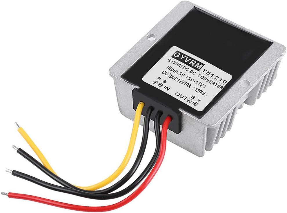
Converter 5V to 12V 10A 120W Boost Power DC to DC Step Up Converter 5V to 12V 10A 120W Boost Power
ARGB Airgoo Computer Fan Controller Commander - Speed Adjustable 3-pin or 4-pin fan - Include Strip PC Software Meeting power demands in modern day electronics is quite a challenge and there are times where we will not be able to supply sufficient voltage for our circuits. In that case we need to go for DC to DC boost converter circuits like these to step up the incoming voltage to a certain usable level. These kinds of step up converter circuits will be useful in Solar powered projects, Lighting systems, Battery powered projects and so. MT3608:With the voltage boost converter module with IC Lm2577-ADJ, you can draw 12V @800mA stable DC voltage output at a wide range of input voltage levels from 3V to 40V. The LM2577 is designed with an 3.0A NPN switch, which is also equipped with a thermal and current limiting protection circuit. EZ DIY FAB also has a converter, but does allow you to use it as 12V connected or as its own controller. Again, have to split the ARGB signal off. Hi Frank, great Blog. I’m looking at building a PCB with 5 of these circuits on side by side with then the V+ & V- out connected together for higher amp. Would I need another Schottky diode at the end of each V+ out circuit before they connect to the other V+ out’s in the circuit? A hub only adds more headers if you have a motherboard with 1 3-pin 5v header. My motherboard has 0 3-pin 5v headers. CPUi7-4790k MotherboardGigabyte Z97N-WIFI RAMG.Skill Sniper DDR3 1866mhz GPUEVGA GTX1080Ti FTW3 CaseCorsair 380T
 Great Deal